Core Product Features
1. 1200V High Voltage Resistance Design
The breakdown voltage has been raised to 1200V, suitable for industrial high-voltage systems, with stable voltage resistance and strong shock resistance.
2. 600A High Current High Power Output
Rated continuous current is 600A, peak current can reach 1200A, meeting the requirements of high-power frequency conversion and drive scenarios.
3. Advanced Structure of Groove Gate/Field Cut-off
Trench Gate + Field Stop structure, reducing conduction loss, improving switching efficiency and reliability.
4. Built-in NTC Temperature Real-time Monitoring
On-board NTC thermistor, supporting precise temperature control, improving the long-term stability of the system.
5. High Short-Circuit Capacity Stronger Safety
Excellent short-circuit current capacity, suitable for industrial heavy loads, frequent start-stop and other high-demand scenarios.
6. Copper Baseplate + Standard Packaging Excellent Heat Dissipation
Lower thermal resistance of the copper baseplate, fast heat dissipation, longer lifespan.
7. Industrial-grade Wide Temperature Stable Operation
Adaptable to harsh environments, suitable for outdoor and industrial sites.
Five Reasons to Choose WISEDRV
1. Original Design - Stable and Controllable Quality
Self-developed IGBT module, from chip design to packaging and testing, full process control ensures high consistency and low failure rate.
2. High Performance and Affordable Price - Stable Supply
High performance, better price, faster delivery, and support for stable batch supply.
3. Rigorous Testing - Reliable Guarantee
Each module passes multiple reliability tests such as insulation withstand voltage, thermal resistance, switching characteristics, and high/low temperature cycling.
4. One-stop Technical Support
Provide application solutions, drive matching suggestions, heat dissipation design guidance, and technical collaboration.
5. Stock Inventory - Mass Production
Regular stock available, supports batch orders, and quick delivery without delaying project cycles.
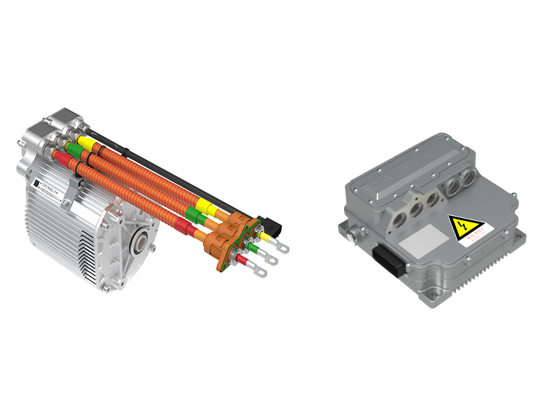
Applicable application scenarios
Frequency Converter
Uninterruptible Power Supply
Motor Drives
Solar Power
Our factory and production capabilities
1. Modern IGBT module packaging production line.
2. Adopting industrial standard packaging structure.
3. Full inspection upon leaving the factory to ensure product consistency.
4. Strict electrostatic protection and dust-free workshop.
5. Equipped with high and low temperature aging and reliability laboratories.
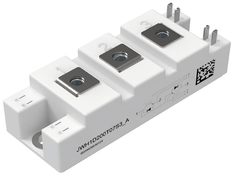
Specification parameters:
IGBT, Inverter
Maximum rated Values
|
Parameter
|
Symbol
|
Conditions
|
Value
|
Unit
|
|
Collector-emitter voltage
|
VCES
|
Tvj=25℃
|
1200
|
V
|
|
Continuous DC forward current
|
IC nom
|
TC=75℃
Tvj max=175℃
|
600
|
A
|
|
Repetitive peak forward current
|
ICRM
|
tp=1 ms
|
1200
|
A
|
|
Total power dissipation
|
Ptot
|
TC=25℃,
Tvj max=175℃
|
2727
|
W
|
|
Gate-emitter peak voltage
|
VGES
|
|
±30
|
V
|
Characteristic Values
|
Parameter
|
Symbol
|
Conditions
|
Value
|
Unit
|
|
MIN.
|
Typ.
|
MAX.
|
|
Collector-emitter saturation voltage
|
VCE(sat)
|
VGE = 15 V,
IC = 600 A
|
Tvj = 25℃
Tvj=125℃
Tvj=150℃
|
-
-
-
|
2.31
2.86
2.98
|
3
-
-
|
V
|
|
Gate threshold voltage
|
VGE(th)
|
IC = 23 mA, VCE = VGE,
Tvj = 25℃
|
4.0
|
6.11
|
7.0
|
V
|
|
Collector-emitter cut-off current
|
ICES
|
VCE = 1200 V ,VGE = 0 V
Tvj = 25℃
|
-
|
-
|
1
|
mA
|
|
Gate-emitter leakage current
|
IGES
|
VCE = 0 V, VGE = 20 V, Tvj = 25℃
|
-
|
-
|
400
|
nA
|
|
Gate charge
|
QG
|
VCC = 600 V, IC = 600 A,
VGE = 15 V
|
-
|
3260
|
-
|
nC
|
|
Turn-on delay time
|
td(on)
|
VCE=600V,
IC = 600A,
VGE = ±15V,
RG= 10.0 Ω
|
Tvj = 25℃
Tvj=125℃
Tvj=150℃
|
-
-
-
|
0.52
0.45
0.43
|
-
-
-
|
μs
|
|
Rise time, inductive load
|
tr
|
Tvj = 25℃
Tvj=125℃
Tvj=150℃
|
-
-
-
|
0.27
0.29
0.30
|
-
-
-
|
|
Turn-off delay time, inductive load
|
td(off)
|
Tvj = 25℃
Tvj=125℃
Tvj=150℃
|
-
-
-
|
1.27
1.33
1.34
|
-
-
-
|
|
Fall time, inductive load
|
tf
|
Tvj = 25℃
Tvj=125℃
Tvj=150℃
|
-
-
-
|
0.51
0.51
0.47
|
-
-
-
|
|
Turn-on energy loss per pulse
|
Eon
|
Tvj = 25℃
Tvj=125℃
Tvj=150℃
|
-
-
-
|
174
220
238
|
-
-
-
|
mJ
|
|
Turn-off energy loss per pulse
|
Eoff
|
Tvj = 25℃
Tvj=125℃
Tvj=150℃
|
-
-
-
|
172
175
169
|
-
-
-
|
|
SC data
|
ISC
|
VGE =15 V,VCC = 600 V
tP = 10 µs, Tvj = 150℃
|
-
|
2734
|
-
|
A
|
|
Thermal resistance, junction-case
|
RthJC
|
per IGBT
|
-
|
-
|
0.055
|
K/W
|
|
Temperature under switching conditions
|
Tvj op
|
|
-40
|
-
|
150
|
℃
|
Diode, Inverter
Maximum ratings Values
|
Parameter
|
Symbol
|
Conditions
|
Value
|
Unit
|
|
Repetitive peak reverse voltage
|
VRRM
|
Tvj=25∘C
|
1200
|
V
|
|
Continuous DC forward current
|
IF
|
|
600
|
A
|
|
Repetitive peak forward current
|
IFRM
|
tp=1 ms
|
1200
|
A
|
Characteristic Values
|
Parameter
|
Symbol
|
Conditions
|
Value
|
Unit
|
|
MIN.
|
Typ.
|
MAX.
|
|
Forward voltage
|
VF
|
VGE = 0V,
IF = 600 A
|
Tvj = 25℃
Tvj=125℃
Tvj=150℃
|
-
-
-
|
2.34
2.39
2.41
|
3.0
-
-
|
V
|
|
Peak reverse recovery current
|
IRM
|
VR = 600 V,
-diF/dt=631A/µs
(Tvj=150°C)
IF= 600 A
VGE=-15 V
|
Tvj = 25℃
Tvj=125℃
Tvj=150℃
|
-
-
-
|
125
205
228
|
-
-
-
|
A
|
|
Recovery charge
|
Qr
|
Tvj = 25℃
Tvj=125℃
Tvj=150℃
|
-
-
-
|
7.70
7.76
7.58
|
-
-
-
|
μC
|
|
Reverse recovery energy per pulse
|
Erec
|
Tvj = 25℃
Tvj=125℃
Tvj=150℃
|
-
-
-
|
6.72
19.3
25.5
|
-
-
-
|
mJ
|
|
Thermal resistance, junction-case
|
RthJC
|
per diode
|
-
|
-
|
0.097
|
K/W
|
|
Temperature under switching conditions
|
Tvj op
|
|
-40
|
-
|
150
|
℃
|
NTC-Thermistor
Characteristic Values
|
Parameter
|
Symbol
|
Conditions
|
Value
|
Unit
|
|
Rated resistance
|
R25
|
TNTC=25℃
|
5.00
|
kΩ
|
|
Deviation of R100
|
|∆R|/R
|
TNTC = 100°C, R100 = 493 Ω
|
5
|
%
|
|
B-value
|
B25/50
|
Calculated from resistance value at 25℃ and 50℃
|
3375
|
K
|
|
B-value
|
B25/80
|
Calculated from resistance value at 25℃ and 80℃
|
3411
|
K
|
|
B-value
|
B25/100
|
Calculated from resistance value at 25℃ and 100℃
|
3433
|
K
|
Module
|
Parameter
|
Symbol
|
Conditions
|
Values
|
Unit
|
|
Isolation test voltage
|
VISOL
|
RMS, f=0 Hz, t=1.2 sec
|
4.7
|
kV
|
|
Material of Module baseplate
|
|
|
Cu
|
|
|
Material of Internal Isolation
|
|
|
Al2O3
|
|
|
Creepage distance
|
|
Terminal to heatsink
Terminal to terminal
|
15.0
13.0
|
mm
|
|
Clearance
|
|
Terminal to heatsink
Terminal to terminal
|
12.5
10.0
|
mm
|
|
Stray inductance module
|
LS
|
|
20
|
nH
|
|
Storage temperature
|
Tstg
|
|
-40 ~125
|
℃
|
|
Mounting torque for module mounting
|
M
|
Screw M5 - Mounting according to valid application note
|
3.0 ~ 6.0
|
N·m
|
|
Terminal connection torque
|
M
|
Screw M6 - Mounting according to valid application note
|
3.0 ~ 6.0
|
N·m
|
|
Weight
|
G
|
|
348
|
g
|
Output characteristic IGBT, Inverter (typical)
IC = f (VCE)
VGE = 15 V

Output characteristic IGBT, Inverter (typical)
IC = f (VCE)
Tvj = 150℃

Transfer characteristic IGBT, Inverter (typical)
IC = f (VGE)
VCE = 20 V

Switching losses IGBT, Inverter (typical)
Eon = f (IC), Eoff = f (IC),
VGE = ±15 V, RG = 10Ω, VCE = 600 V

Transient thermal impedance IGBT, Inverter (typical)
ZthJC = f (t)

Forward characteristic of Diode, Inverter (typical)
IF = f (VF)

Transient thermal impedance Diode, Inverter (typical)
ZthJC = f (t)

Switching losses Diode, Inverter (typical)
Erec = f (IF), Ron = 10.0Ω,VCE = 600 V

Circuit_diagram_headline

Package outlines

Unit:mm


 Product categories