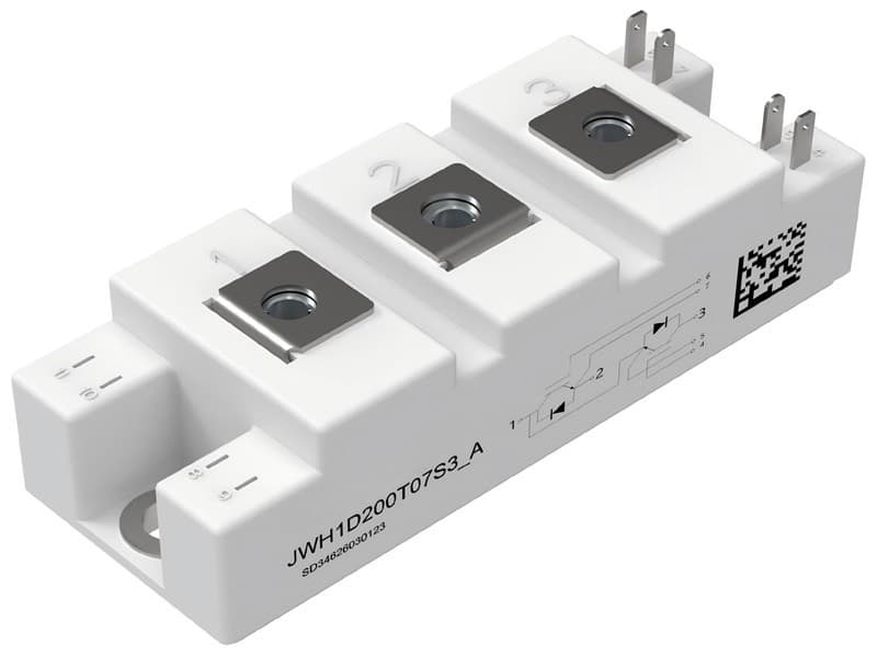
1. Advanced Chip Architecture
Utilizes trench gate / field cutoff structure IGBT, designed by the original manufacturer.
2. Mechanical Characteristics
Copper substrate heat dissipation
Industrial standard packaging
3. Wide temperature range and high reliability
The operating junction temperature reaches 150℃, suitable for harsh industrial environments.
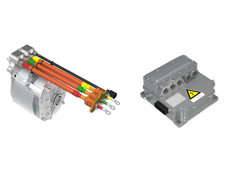
4.Typical Application Uninterruptible Power Supply
Motor drive Servo drive
Electric welding machine
Why choose us (differential advantage)?
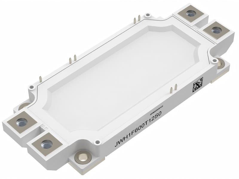
1.We have independently developed the structure
The parameters are truly reliable. We use the trench gate / field cutoff structure IGBT, with a 650V/400A specification. The switching loss, thermal resistance, and short-circuit current are all the actual measured parameters by the original factory, and the data is transparent and accessible.
2. Batch traceability, good batch consistency
The module is equipped with a production batch, date code, and serial number traceability system. The parameter consistency is strong, meeting the requirements for stable delivery of large quantities of industrial equipment.
3. Copper substrate with low thermal resistance, excellent heat dissipation performance
With the copper substrate design, the heat dissipation efficiency is high, and it can operate stably at a working junction temperature of 150℃ for a long time.
IGBT, Inverter
Maximum rated Values
|
Parameter
|
Symbol
|
Conditions
|
Values
|
Unit
|
|
Collector-emitter voltage
|
V CES |
Tvj = 25℃
|
650
|
V
|
|
Continuous DC collector current
|
IC nom |
TC=90℃,
Tvj max = 175℃
|
400
|
A
|
|
Repetitive peak collector current
|
ICRM |
tp=1 ms
|
800
|
A
|
|
Total power dissipation
|
Ptot
|
TC= 25℃,
Tvj max= 175℃
|
1127
|
W
|
|
Gate-emitter peak voltage
|
VGES |
|
±20
|
V
|
Characteristic Values
|
Parameter
|
Symbol
|
Conditions
|
Values
|
Unit
|
|
Min.
|
Typ.
|
Max.
|
|
Collector-emitter saturation voltage
|
VCE(SAT) |
VGE = 15V,
IC= 400 A
|
Tvj= 25℃
Tvj = 125℃
Tvj = 150℃
|
-
-
-
|
1.50
1.57
1.60
|
2.0
-
-
|
V
|
|
Gate threshold voltage
|
VGE(th) |
IC=23mA,
VCE=VGE,
T vj=25℃
|
4.0
|
5.42
|
7.0
|
V
|
|
Collector-emitter cut-off current
|
IGES |
VCE=650 V,
VGE =0 V,
T vj=25℃
|
-
|
-
|
1
|
mA
|
|
Gate-emitter leakage current
|
IGSE |
VCE=0 V,
VGE=20 V,
T vj=25℃
|
-
|
-
|
400
|
nA
|
|
Turn-on delay time
|
td(on)
|
VCE= 350 V ,
IC= 400 A,
VGE=±15 V,
RG=10 Ω
|
Tvj = 25℃
Tvj = 125℃ Tvj = 150℃
|
-
-
-
|
0.25
0.23
0.22
|
-
-
-
|
µs
|
|
Rise time,inductive load
|
tr
|
Tvj = 25℃
Tvj = 125℃ Tvj = 150℃
|
-
-
-
|
0.85
0.83
0.81
|
-
-
-
|
|
Turn-off delay time,inductive load
|
td(off)
|
Tvj = 25℃
Tvj = 125℃ Tvj = 150℃
|
-
-
-
|
0.40
0.43
0.44
|
-
-
-
|
|
Fall time,inductive load
|
tf
|
Tvj = 25℃
Tvj = 125℃ Tvj = 150℃
|
-
-
-
|
0.16
0.19
0.20
|
-
-
-
|
|
Turn-on energy loss per pulse
|
Eon
|
Tvj = 25℃
Tvj = 125℃ Tvj = 150℃
|
-
-
-
|
110
110
110
|
-
-
-
|
mJ
|
|
Turn-off energylossperpulse
|
Eoff
|
Tvj = 25℃
Tvj = 125℃ Tvj = 150℃
|
-
-
-
|
13.1
25.1
32.8
|
-
-
-
|
|
SC data
|
ISC |
VGE=15V,VCC=350V
tP=10 µs,Tvj=150℃
|
-
|
1981
|
-
|
A
|
|
Thermal resistance,junction-case
|
RthJC
|
per IGBT
|
-
|
-
|
0.133
|
K/W
|
|
Temperatureunder switching conditions
|
Tvj op
|
|
-40
|
-
|
150
|
℃
|
Diode, Inverter
Maximum ratings Values
|
Parameter
|
Symbol
|
Conditions
|
Values
|
Unit
|
|
Repetitive peak reverse voltage
|
VRRM
|
Tvj = 25°C
|
650
|
V
|
|
Continuous DC forward current
|
IF
|
|
400
|
A
|
|
Repetitive peak forward current
|
IFRM
|
tp = 1 ms
|
800
|
A
|
Characteristic Values
|
Parameter
|
Symbol
|
Conditions
|
Values
|
Unit
|
|
Min.
|
Typ.
|
Max.
|
|
Forward voltage
|
VF
|
V GE= 0 V,
IF = 400 A
|
Tvj = 25℃
Tvj=125℃
Tvj= 150℃
|
-
-
-
|
1.64
1.40
1.35
|
2.5
-
-
|
V
|
|
Peak reverse recovery current
|
IRM
|
VR = 350 V,
IF = 400 A
|
Tvj = 25℃
Tvj=125℃
Tvj= 150℃
|
-
-
-
|
12
31
39
|
-
-
-
|
A
|
|
Recovery charge
|
Qr
|
Tvj = 25℃
Tvj=125℃
Tvj= 150℃
|
-
-
-
|
0.83
1.43
1.53
|
-
-
-
|
µC
|
|
Reverse recovery energy per pulse
|
Erec
|
IF = 400 A,
VR = 350 V,
VGE = -15 V
|
Tvj = 25℃
Tvj=125℃
Tvj= 150℃
|
-
-
-
|
0.32
0.90
1.79
|
-
-
-
|
mJ
|
|
Thermal resistance, junction-case
|
RthJC
|
per diode
|
-
|
-
|
K/W
|
|
Temperature under switching conditions
|
Tvj op
|
|
-40
|
-
|
|
℃
|
Module
|
Parameter
|
Symbol
|
Conditions
|
Values
|
Unit
|
|
Isolation test voltage
|
VISOL
|
RMS,f = 50 Hz, t = 1 min
|
2.7 |
kV |
|
Material of Module baseplate
|
|
|
Cu
|
|
|
Material of Internal Isolation
|
|
|
Al2O3
|
|
|
Stray inductance module
|
LS |
|
35 |
nH
|
| Storage temperature |
Tstg |
|
-40~125
|
℃
|
|
Mounting torque for module mounting
|
M |
Screw M5 - Mounting according to valid application note
|
2.5~3.5
|
N·m
|
|
Terminal connection torque
|
M |
Screw M5 - Mounting according to valid application note
|
2.5~3.5
|
N·m
|
|
Weight
|
G |
|
200 |
g
|
Output characteristic IGBT,Inverter(typical)
IC = f (VCE)
VGE = 15 V

Output characteristic IGBT,Inverter(typical)
IC = f (VCE)
Tvj = 150℃
Transfer characteristic IGBT, Inverter (typical)
IC = f (VGE)
VCE = 20 V 
Switching losses IGBT, Inverter (typical)
Eon = f (IC), Eoff = f (IC),
VGE = ±15 V, RG=10Ω, VCE =350 V
Transient thermal impedance IGBT, Inverter (typical)
ZthJC = f (t) 
Forward characteristic of Diode, Inverter (typical)
IF = f (VF)
Transient thermal impedance Diode, Inverter (typical)
ZthJC = f (t) 
Switching losses Diode, Inverter (typical)
Erec = f (IF), RGon = 10 Ω, VCE = 350 V

Circuit_diagram_headline

Package outlines


单位:mm


 Product categories