-
-
 Low loss and high efficiency
Using a trench gate / non-through structure, the switching loss has been tested and calibrated. It has low loss and more efficient system operation.
-
Excellent heat dissipation and long lifespan
By using a copper substrate and an internal Al₂O₃ insulation structure, the heat dissipation efficiency is high and the insulation performance is reliable, ensuring the long-term stable operation of the module.
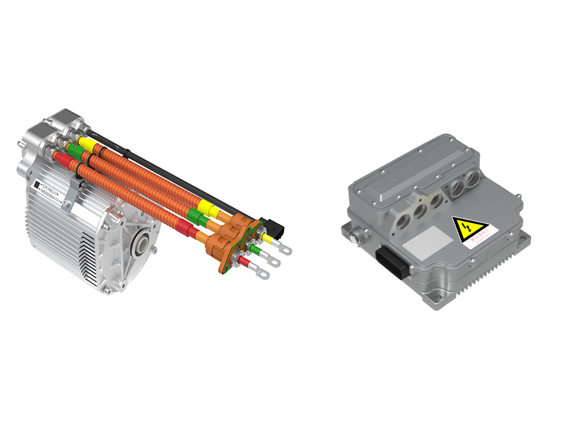
1.Frequency converter
2.Uninterruptible Power Supply
3.Motor drive
4.Electric welding machine
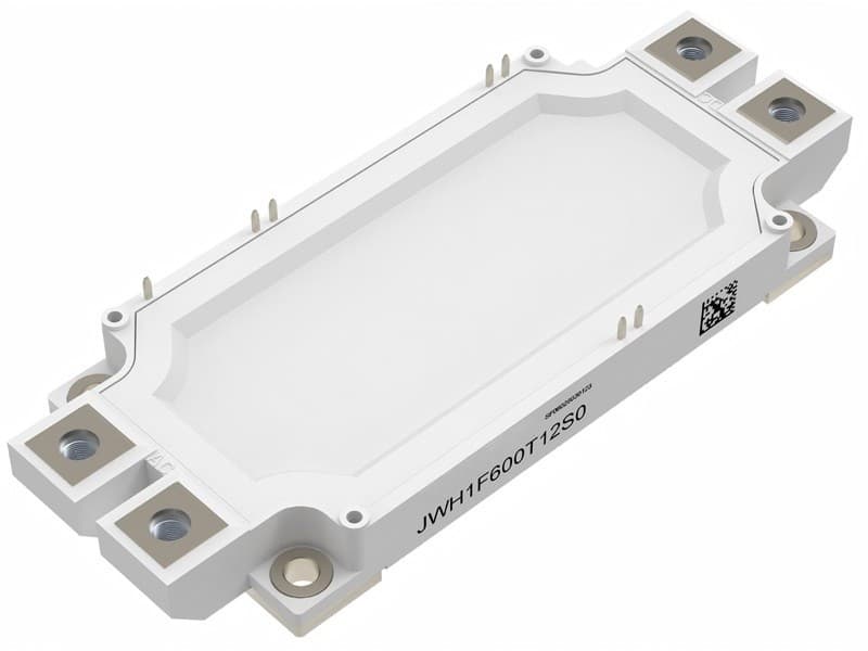
Q1: How many power devices can this module support?
A: 650V/200A specification, suitable for several thousand kW level medium to large power inverters / drives.
Q2: What is the working temperature range?
A: Working junction temperature range -40℃ ~ 150℃, ensuring reliable operation in industrial-grade high and low temperature environments.
Q3: What are the protection and safety features?
A: 2.5kV insulation withstand voltage, 10mm creepage distance, high short-circuit capacity, wide temperature range reliability, meeting industrial safety standards.
Specification parameters:
IGBT, Inverter
Maximum rated Values
|
Parameter
|
Symbol
|
Conditions
|
Values
|
Unit
|
|
Collector-emitter voltage
|
VCES
|
Tvj = 25℃
|
650
|
V
|
|
Continuous DC collector current
|
IC nom
|
TC = 70℃,
Tvj max =150℃
|
200
|
A
|
|
Repetitive peak collector current
|
ICRM
|
tP=1 ms
|
400
|
A
|
|
Total power dissipation
|
Ptot
|
TC = 25℃,
Tvj max = 150℃
|
698
|
W
|
|
Gate-emitter peak voltage
|
VGES
|
-
|
±20
|
V
|
Characteristic Values
|
Parameter
|
Symbol
|
Conditions
|
Values
|
Unit
|
|
Min.
|
Typ.
|
Max.
|
|
Collector-emitter saturation voltage
|
VCE(sat)
|
VGE =15V,
IC = 200A
|
Tvj= 25℃
Tvj= 125℃
Tvj= 150℃
|
-
-
-
|
1.70
2.00
2.10
|
1.9
-
-
|
V
|
|
Gate threshold voltage
|
VGE(th)
|
IC =3.2 mA,
VCE = VGE,
Tvj = 25℃
|
5.0
|
5.832
|
6.8
|
V
|
|
Internalgate resistor
|
RGint
|
Tvj = 25℃
|
-
|
2
|
-
|
Ω
|
|
Collector-emitter cut-off current
|
ICES
|
VCE= 650 V ,
VGE = 0V
Tvj = 25℃
|
-
|
-
|
0.1
|
mA
|
|
Gate-emitter leakage current
|
IGES
|
VCE = 0 V,
VGE = 20 V,
Tvj = 25℃
|
-
|
-
|
500
|
nA
|
|
Input capacitance
|
Cies
|
VCE = 25 V, VGE = 0V,
f = 1 MHz,Tvj = 25℃
|
-
|
15000
|
-
|
pF
|
|
Reverse transfer capacitance
|
Cres
|
-
|
280
|
-
|
pF
|
|
Turn-on delay time
|
td(on)
|
VCE = 300 V,
IC = 200A,
VGE = ±15 V,
RG =4.7 Ω
|
Tvj = 25℃
Tvj = 125℃
Tvj = 150℃
|
-
-
-
|
0.106
0.116
0.118
|
-
-
-
|
μs
|
|
Rise time, inductive load
|
tr
|
Tvj = 25℃
Tvj = 125℃
Tvj = 150℃
|
-
-
-
|
0.103
0.109
0.11
|
-
-
-
|
|
Turn-off delay time, inductive load
|
td(off)
|
Tvj = 25℃
Tvj = 125℃
Tvj = 150℃
|
-
-
-
|
0.165
0.177
0.179
|
-
-
-
|
|
Fall time, inductive load
|
tf
|
Tvj = 25℃
Tvj = 125℃
Tvj = 150℃
|
-
-
-
|
0.084
0.096
0.1
|
-
-
-
|
|
Turn-on energy loss per pulse
|
Eon
|
Tvj = 25℃
Tvj = 125℃
Tvj = 150℃
|
-
-
-
|
1.591
3.045
3.442
|
-
-
-
|
mJ
|
|
Turn-off energy loss per pulse
|
Eoff
|
Tvj = 25℃
Tvj = 125℃
Tvj = 150℃
|
-
-
-
|
4.458
5.176
5.37
|
-
-
-
|
|
SC data
|
Isc
|
VGE = 15 V,VCC = 300 V
tP = 10 µs, Tvj = 150℃
|
-
|
960
|
-
|
A
|
|
Thermal resistance, junction-case
|
RthJC
|
per IGBT
|
-
|
-
|
0.179
|
K/W
|
|
Temperature under switching conditions
|
Tvj op
|
|
-40
|
-
|
150
|
℃
|
Diode, Inverter
Maximum ratings Values
|
Parameter
|
Symbol
|
Conditions
|
Values
|
Unit
|
|
Repetitive peak reverse voltage
|
VRRM
|
Tvj=25∘C
|
650
|
V
|
|
Continuous DC forward current
|
IF
|
|
200
|
A
|
|
Repetitive peak forward current
|
IFRM
|
tp=1ms
|
400
|
A
|
Characteristic Values
|
Parameter
|
Symbol
|
Conditions
|
Values
|
Unit
|
|
Min.
|
Typ.
|
Max.
|
|
Forward voltage
|
VF
|
VGE = 0 V,
IF = 200 A
|
Tvj = 25℃
Tvj = 125℃
Tvj = 150℃
|
-
-
-
|
1.661
1.682
1.651
|
2.25
-
-
|
V
|
|
Peak reverse recovery current
|
IRM
|
VR=300V,
IF =200A,
dIF/dt=5400A/µs
|
Tvj = 25℃
Tvj = 125℃
Tvj = 150℃
|
-
-
-
|
76
85
89
|
-
-
-
|
A
|
|
Recovery charge
|
Qr
|
Tvj = 25℃
Tvj = 125℃
Tvj = 150℃
|
-
-
-
|
5.251
6.226
6.455
|
-
-
-
|
µC
|
|
Reverse recovery energy per pulse
|
Erec
|
IF =200A,
VR = 300V,
VGE = -15V
|
Tvj = 25℃
Tvj = 125℃
Tvj = 150℃
|
-
-
-
|
1.298
2.049
2.382
|
-
-
-
|
mJ
|
|
Thermal resistance, junction-case
|
RthJC
|
per diode
|
-
|
-
|
0.303
|
K/W
|
|
Temperature over switching conditions
|
Tvj op
|
|
-40
|
-
|
150
|
℃
|
Module
|
Parameter
|
Symbol
|
Conditions
|
Values
|
Unit
|
|
Isolation test voltage
|
VISOL
|
|
2.5
|
kV
|
|
Material of Module baseplate
|
|
|
Cu
|
|
|
Material of Internal Isolation
|
|
|
Al2O3
|
|
|
Creepage distance
|
|
Terminal to heatsink
|
10.0
|
mm
|
|
Stray inductance module
|
Ls
|
|
35
|
nH
|
|
Storage temperature
|
Tstg
|
|
−40∼125
|
∘C
|
|
Mounting torque for module mounting
|
M
|
Screw M6 - Mounting
according to valid application note
|
3.0 ~ 6.0
|
N·m
|
|
Terminal connection torque
|
M
|
Screw M5 - Mounting
according to valid application note
|
3.0 ~ 6.0
|
N·m
|
|
Weight
|
G
|
|
163
|
g
|
Output characteristic IGBT, Inverter (typical)
IC = f (VCE)
VGE = 15 V

Output characteristic IGBT, Inverter (typical)
IC = f (VCE)
Tvj = 150℃

Transfer characteristic IGBT, Inverter (typical)
IC = f (VGE)
VCE = 20 V

Switching losses IGBT, Inverter (typical)
Eon = f (IC), Eoff = f (IC),
VGE = ±15 V, Ron = 4.7 Ω, Roff = 4.7 Ω, VCE = 300 V

Transient thermal impedance IGBT, Inverter (typical)
ZthJC = f (t)

Forward characteristic of Diode, Inverter (typical)
IF = f (VF)

Transient thermal impedance Diode, Inverter (typical)
ZthJC = f (t)

Switching losses Diode, Inverter (typical)
Erec = f (IF), RGon = 4.7 Ω, VCE = 300 V

Circuit_diagram_headline

Package outlines

Unit:mm


 Product categories